Singularities - what's the big deal?
Now and again you may see an FE guru tell you to worry about singularities in your FE model. There follows a short explanation of this phenomenon.
So what is it?
Well in cosmology it's a black hole (infinite density over zero volume) and in mathematics it's a divide by zero but in Finite Element models it's a region of your model which keeps increasing in stress each time you make the mesh there finer. This happens at unradiused cracks and sharp corners. You are literally trying to approximate infinity by trying to emulate a stress, ie force/area with the area tending towards zero. We'll call this Type 1 singularity (see diagram below).
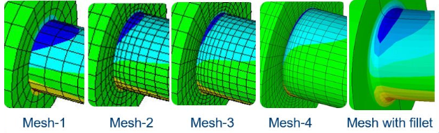
Type 1 singularity: Chasing an infinite stress - somewhat avoided by adding a fillet
You also get Type 2 singularities with point loads/restraints on a solid model, Again this is due to dividing a load by zero area. A related Type 3 singularity occurs in, for example, fixing an end of a cantilever beam and ignoring the fact that Poissons ratio forces it to also shrink as it being pulled/bent - as in real life - which causes high local stresses. These user errors stem from classroom memories of simplistic free-body diagrams of rigid bodies which have no annoying complications such as local deformations. So to avoid this always distribute your load/restraint over an area rather than a point and create your restraints to allow your part to deform naturally - as in real-life! Only Type 1 singularities will be discussed further.
So should you care about it?
Despite what you may read, most of the time you don't have to worry about Type 1 singularities as long as you recognise that is what they are. This is because that infinite stress would actually be mathematically correct if the material was truly infinitely elastic - which is the assumption made in elastic analysis. Simply put, if the assumption is wrong then so is the result. Put another way, those high stresses at the sharp corner are entirely fictitious once they go above the yield strength. We make the infinite elasticity assumption purely to save computing time as it should be correct for much of the structure if the part has been designed correctly. If we used a more correct assumption, such as elasticity up to the yield point then plasticity after it, then the singularity disappears. In such 'plastic analysis' the element interior stresses (called gauss point stresses) which go above the yield point (according to the von Mises yield criterion) are marked as plastic and the extra force that would be taken by them is then distributed among the neighbouring elements (using a flow rule) so that the extent of the yielded zone then increases. If the yield zone spreads over an entire thickness then plastic collapse occurs. So a plastic limit analysis of the part would produce the same maximum load regardless of the fineness of the mesh at the corner.
So for general monotonic loading we can ignore that stress concentration and a radius is not usually required at a singularity. Those academic 'gurus' worried about it have usually never done a stress assessment in their lives or dealt much with plasticity.
However, for cyclic loading it is a different matter because then those sites of high stress concentration are likely to be sites of fatigue failure. With older fatigue curves we used to have to add a radius to the Finite Element model and increase the fineness of the radiused area until we achieved an assymtotic value which would then be used in the stress amplitude or range calculation required for the fatigue curve* y-axis. Alternatively we were allowed to calculate a linearised stress and apply a stress concentration factor (SCF) to obtain a stress amplitude/range, However modern fatigue curves now incorporate stress concentrations according to the weld details (based on tests) so we calculate a 'structural stress' (often a linearised stress through the section) and use that directly in the fatigue curve.
Hence for most modern fatigue calculations there is no need to worry about singularities either. One exception to this is the RCC-MR French nuclear design code where you currently must find a linearised strain for the strain-based fatigue curves (using a stress with an SCF) but I'd expect this code will fall into line with other design codes at some future point.
Note that I am not implying you can avoid adding fillet radii on the real part. Quite the opposite! The bigger the radius on a corner, the better, especially if cyclic loading is present! But for the narrower purpose of stress/strain assessment of the Finite Element model you no longer have to refine the high stressed area of the FE model to such an extent as previously and for basic scantling calculations you don't really need a fillet in your model at all.
Note also that fillet welds are a different case. For fillet welds in areas of concern I will also model the gap behind the weld and refine that locally to achieve at least two elements through the weld for plastic limit analysis and/or structural stress calculations. The alternative to this is to use a shell/beam model, obtain the reaction forces then do a standard fillet weld group calculation where all stresses are reduced to a single equivalent shear stress. You would need to use Femdesigner Classic to obtain such reaction forces but it is rather more long-winded than using solid models because any time saved in running the model is dwarfed by the much larger pre/post-processing times.
*Fatigue curves are almost all stress range/amplitude versus number-of-cycles (N). However, the high stresses on those graphs must also be fictitious if above the yield stress. This may seem odd if you think about it. It happens because tests used specimens of known cross-sectional area so the stress is calculated simply from load/area. Hence those higher stresses would naturally encapsulate the beginning of plastic collapse seen on a tensile or bending test prior to rupture but it is disguised as an elastic stress by the load/area definition. You should never be in that region because that would be a really bad design.